
Products
Custom Drawn Fast-Axis Lenses
Collimated Holes, Inc. draws custom fast-axis collimator (FAC) lenses and other custom glass lens profiles from customer-provided preforms or from preforms fabricated to customer-defined optical surface equations. The two-dimensional lens cross-section is reproduced continuously along the draw axis.
Customer-provided finished preforms are the most common starting point. When needed, CHI can also coordinate with specialty glass CNC and polishing suppliers to fabricate a preform from customer-provided equations, drawings, or CAD geometry.
Because the lens profile is continuous along the draw axis, the optical function is defined by the cross-section of the drawn structure. Cylindrical, plano, acylindrical, positive-curvature, negative-curvature, and more complex equation-defined surfaces can be reproduced at greatly reduced scale while retaining the essential geometry of the original preform.
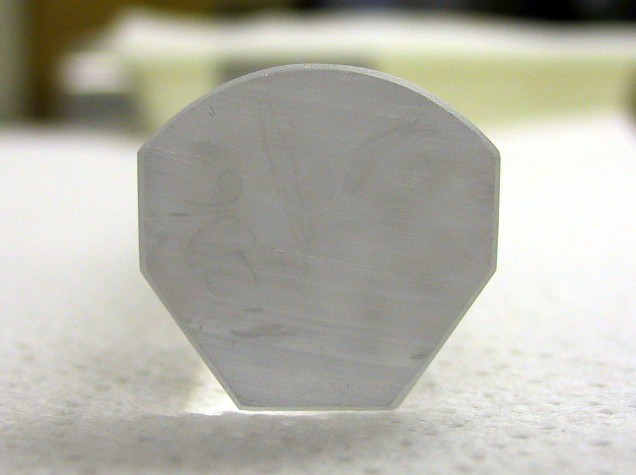
Optical Glass Drawn Lens Preform Cross-section
How the Drawn-Lens Process Works
A drawn lens begins as a much larger glass preform containing the desired finished-lens cross-section.
The preform is heated above its softening temperature and drawn to a smaller cross-section. The relationship between preform feed rate and draw rate determines the reduction ratio, allowing the macroscopic preform geometry to be reproduced at microlens scale.
For example, a profile approximately 40–50 mm across may be reduced to a finished cross-section of hundreds of micrometers or smaller.
The resulting optical surfaces are formed directly during the draw and emerge fire-polished. No subsequent polishing or shaping of the curved optical surfaces is required. The finished cross-sectional profile remains very close to a geometrically scaled version of the starting preform.
Fast-Axis Collimation and Single-Axis Lensing
Fast-axis collimator lenses are commonly used near laser-diode emitters and bars, where divergence along one axis is much greater than along the perpendicular axis.
Unlike a conventional spherical camera lens, a drawn FAC lens is uniform along its length. Its optical profile is defined in the transverse cross-section and remains constant along the draw axis, producing optical power in one transverse axis rather than rotationally symmetric lensing.
Laser-diode fast-axis collimation is a major application, but the same manufacturing approach can be used for a broad range of single-axis beam-shaping, focusing, combining, illumination, and imaging functions.
Custom Cross-Sectional Profiles
Drawn lenses are not limited to conventional cylindrical forms. The input and output surfaces do not need to be symmetric or use the same type of curvature. For complex prescriptions, the practical limitation is generally whether the large-scale preform can be accurately manufactured and whether the geometry remains stable during drawing.
- Cylindrical lenses
- Plano-cylindrical or “D”-shaped lenses
- Positive and negative curvature combinations
- Polynomial-defined acylindrical surfaces
- Plano, cylindrical, or equation-defined input surfaces paired independently with different output surfaces
- Curved-chevron and other asymmetric cross-sections
- Composite optical structures containing multiple compatible glasses
- Separate drawn glass spacers, supports, mounting elements, and alignment features
- Integrated optical, mounting, mechanical, or alignment features incorporated directly into the drawn cross-section
Profile Fidelity and Iterative Compensation
The draw process preserves the starting profile very closely, although small amounts of deformation can occur as the softened glass flows.
For demanding applications, customers may characterize the cross-section produced during an initial prototype draw using high-resolution metrology. The measured deformation can then be incorporated into a revised preform design so that predictable draw-induced changes move the finished lens toward the desired optical profile rather than away from it.
CHI specializes in glass drawing and process development rather than optical prescription design or high-resolution optical-surface metrology. Customers normally provide the required surface prescription and perform detailed characterization of the prototype lens geometry and optical performance.
Optical Glass Selection
CHI can draw a wide range of optical glasses provided they are compatible with the thermal and mechanical requirements of the draw process. Suitable materials can include crown, flint, borosilicate, lead-containing, high-index, and other specialty optical glasses.
Fused silica cannot be drawn with CHI’s current equipment because its required processing temperature exceeds the operating range of the draw towers. Some high-index and heavily doped optical glasses can be prone to devitrification; CHI has worked with customers to test candidate glasses and identify materials that provide the desired optical properties while maintaining acceptable process stability.
- Softening temperature compatible with CHI draw equipment, generally below approximately 900 °C
- Resistance to devitrification during heating, drawing, and cooling
- Adequate mechanical behavior and tensile strength during drawing
- Optical transmission and refractive-index requirements
- Compatibility with other glasses when a composite structure is required
Single-Glass and Composite Structures
Most drawn FAC lenses are homogeneous single-glass structures, but the draw process can also support more complex assemblies made from thermally compatible glasses. Only compatible glass materials can pass through the draw process. Optical coatings are applied after drawing rather than incorporated into the preform.
- Multi-glass optical structures
- Preassembled composite preforms
- Integrated lens-and-mounting structures
- Separate drawn spacers and mechanical elements
- Mounting, mechanical, or alignment features incorporated directly into the cross-section
High Production Output From a Single Preform
One of the major advantages of the draw process is the amount of small lens material that can be produced from a single precision preform. Glass volume is substantially conserved during drawing: volume in ≈ volume out, minus process losses.
As cross-sectional dimensions decrease, available output length increases rapidly. For geometrically similar structures, output length scales approximately with the square of the cross-sectional reduction ratio.
For example, a preform approximately 40–50 mm across and 12 inches long may produce enough drawn material for thousands, tens of thousands, or more individual lenses, depending on the final lens cross-section and finished part length.
The same preform can potentially produce more than one final lens size by changing the relationship between preform feed rate and draw rate.
Prototype Through Production
CHI supports both one-off developmental work and high-volume production. The principal early program costs are usually associated with precision preform design and fabrication, followed by draw development. Once the preform and draw process are established, the ability to produce very large amounts of lens material from a single preform can make the approach particularly attractive for production quantities.
- Customer definition of the required optical prescription
- Customer supply of a finished preform, or fabrication of a preform from customer-provided equations or drawings
- Prototype drawing at one or more reduction ratios
- Customer characterization of the resulting lens profile and optical performance
- Preform adjustment, if necessary, to compensate for systematic draw deformation
- Final draw development and dimensional optimization
- Repeat production from the approved preform geometry
Supplied Form, Finishing, Dicing, and Coating
CHI’s preferred delivered product is raw drawn lens material in longer usable lengths, allowing the customer to perform coating, dicing, cleaning, and final packaging according to the requirements of the finished assembly.
Individual drawn lengths are packaged in separate slots of plastic corrugated material to minimize contact, scratching, and chipping while allowing individual pieces to be removed as needed.
The cut ends along the draw axis normally do not participate in the FAC optical function. Dicing-blade or wire-saw cutting therefore commonly provides an adequate end condition without subsequent optical polishing.
- Dicing or wire-saw cutting
- Short finished lengths
- Optical coatings through outside specialty suppliers
- Cleaning and specialized packaging
- Mounting or integration into larger assemblies
Representative Size Capability
| Parameter | Representative CHI Capability |
|---|---|
| Cross-sectional size | Approximately 50 µm at the practical small end to tens of millimeters at the large end, depending on glass, geometry, draw tension, and required reduction ratio. |
| Dimensional tolerance | For a lens several hundred micrometers across, a representative standard overall dimensional tolerance is approximately ±10 µm. Tighter control may be possible when required. |
| Supplied length | CHI commonly supplies drawn lens material in usable lengths ranging from approximately 6 inches to 0.5 meter. Shorter finished pieces can also be produced. |
Information to Include With an Inquiry
- Intended optical function and application
- Customer-defined lens prescription or surface equations
- Preform drawing or CAD geometry
- Whether the customer will supply the finished preform
- Desired finished cross-sectional dimensions
- Required dimensional tolerance
- Optical glass type or relevant optical properties
- Required raw drawn length or finished part length
- Expected prototype and production quantities
- Any coating, dicing, mounting, packaging, or downstream-processing requirements
Frequently Asked Questions
Can CHI work from customer-provided optical equations or drawings?
Yes. Customer-supplied finished preforms are the most common starting point, but CHI can also coordinate fabrication of a polished glass preform from customer-provided cylindrical, acylindrical, polynomial, or other surface definitions. The customer remains responsible for defining the optical prescription.
Can highly precise profiles be developed through iterative drawing?
Yes. The finished cross-section is a very close geometrically reduced version of the starting preform, although small systematic deformation can occur during drawing. For demanding applications, customers can characterize an initial draw and modify the next preform so that predictable draw deformation brings the finished lens closer to the intended profile.
Do the curved optical surfaces require polishing after drawing?
No. The optical surfaces are formed while the glass is hot and emerge fire-polished from the draw process. Subsequent polishing or reshaping of these small drawn optical surfaces is normally neither necessary nor practical.
Can CHI draw a variety of optical glasses?
Yes. CHI can evaluate a wide range of crown, flint, borosilicate, lead-containing, high-index, and specialty optical glasses that have suitable thermal and mechanical behavior during drawing. Fused silica is outside the thermal range of CHI’s current draw equipment.
Can CHI produce more than one lens size from the same preform?
Yes. Different reduction ratios can be produced by changing feed and draw conditions. The resulting lenses retain substantially the same geometry at different cross-sectional scales.
Can CHI provide dicing, coating, or other downstream processing when required?
Yes. CHI can evaluate dicing, coating through outside specialty suppliers, cleaning, packaging, mounting, and related processing on a case-by-case basis. CHI’s primary strength and preferred scope is supplying accurately drawn lens material for customers to integrate into their own downstream production processes.
Can drawn lenses be used for applications other than laser-diode fast-axis collimation?
Yes. Laser-diode FAC is a major application, but the same process can produce custom single-axis lens profiles for beam shaping, focusing, combining, illumination, imaging, and other optical systems.
Can CHI support both prototype development and high-volume production?
Yes. CHI routinely supports projects ranging from one-off developmental work through repeat production. Drawing can be especially advantageous at larger volumes because a single precision preform can generate substantial quantities of geometrically consistent lens material.
Discuss a Drawn-Lens Requirement
Send the desired optical cross-section or surface equations, preform information, glass requirements, finished dimensions, tolerance, required length, and expected quantity. CHI can evaluate glass compatibility, preform fabrication if needed, draw feasibility, and the most practical development path.
Discuss a drawn-lens requirement