
Products
Custom Fiber Optic Faceplates
A fiber optic faceplate (FOFP) is a coherent plate containing many fused optical fibers. It transfers an image point by point from one polished face to the other, allowing a detector, phosphor, vacuum device, or optical assembly to be coupled with effectively zero free-space propagation distance.
A fiber optic faceplate (FOFP) is a coherent plate containing many fused optical fibers. It transfers an image point by point from one polished face to the other, allowing a detector, phosphor, vacuum device, or optical assembly to be coupled with effectively zero free-space propagation distance.
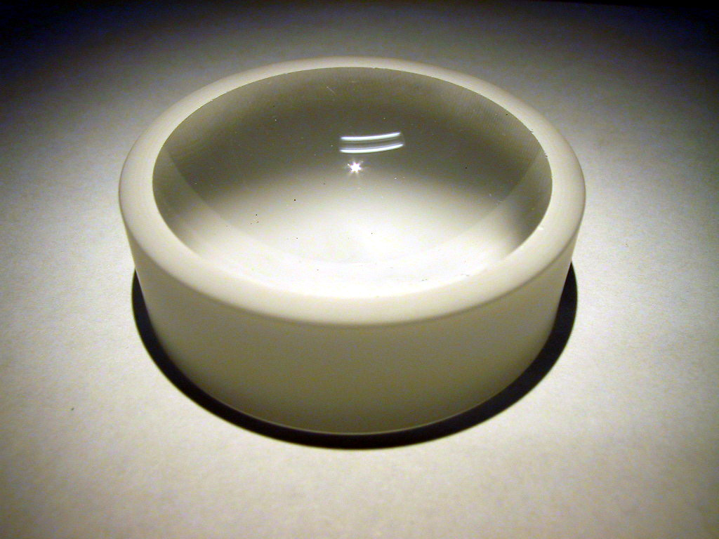
Plano-Concave Radial Field Flattening Fiber Optic Face Plate
How a Faceplate Works
Each constituent fiber acts as an independent light channel. Because the fibers retain their relative positions through the plate, the input pattern is reproduced at the output surface. Constituent-fiber diameter, numerical aperture, open area ratio, EMA, plate thickness, polish, and distortion determine the useful image-transfer performance.
Common Uses for Fiber Optic Face Plates
Faceplates support a range of detector-coupling and imaging applications.
- Direct coupling between a phosphor or scintillator and an image sensor
- Image transfer through a pressure, vacuum, or voltage-isolation boundary
- Detector windows and zero-depth optical interfaces
- Substrates for phosphor screens and radiation-imaging assemblies
- Electron microscopy and other charged-particle instruments
- Medical, scientific, industrial, and aerospace imaging systems
How Faceplates Are Manufactured
Individual fibers are assembled into a coherent multi-fiber structure and fused into a larger block or boule. Plates are sliced from the boule, then ground and polished to the required thickness and exterior size. Depending on the application, faces can be shaped, coated, bonded, or incorporated into a larger subassembly.
Representative Capabilities
| Variable | Representative CHI Capability |
|---|---|
| Construction | Coherent multi-fiber blocks fused under heat and pressure, then sliced, ground, and polished into individual plates. |
| Plan dimensions | Our capability extends from parts a few hundred micrometers across to approximately 200–300 mm square. |
| Thickness | Produceable range extends from a practical minimum near 50–100 µm to more than 100 mm, depending on cross-sectional size and design. |
| Fiber architecture | Custom constituent-fiber diameter, numerical aperture, OAR, glass types, and optional EMA. |
| Surface options | Flat (or limited shaped) polished faces; optical coatings may be coordinated when compatible with the substrate and application. |
| Exterior geometry | Round, square, rectangular, or application-specific profiles, subject to boule size and finishing constraints. |
Design Considerations
| Consideration | Why It Matters |
|---|---|
| Constituent fiber diameter | Sets the spatial sampling scale and influences achievable resolution. |
| Plate thickness | Affects mechanical behavior, attenuation, cross-talk path length, and assembly geometry. |
| Numerical aperture | Controls accepted and transmitted ray angles and should match adjacent optics or emitters. |
| EMA | Can improve contrast by absorbing stray light, at the cost of some active area and output. |
| Distortion and shear | Coherent image transfer requires control of fiber placement and boule deformation. |
| Surface finish and coating | Directly affect coupling loss, bonding, reflection, and compatibility with detectors or phosphors. |
Information to Include With an Inquiry
- Active area and exterior dimensions
- Thickness and mechanical interface
- Target resolution or constituent-fiber diameter
- Wavelength range, numerical aperture, and adjacent optical media
- Contrast, cross-talk, distortion, or shear requirements
- EMA requirement
- Flatness, parallelism, polish, edge, coating, and bonding requirements
- Radiation, vacuum, temperature, or voltage environment
- Prototype and production quantities
Frequently Asked Questions
Is a faceplate the same as a window?
A conventional window transmits light through bulk material and allows free-space spreading within the thickness. A coherent fiber optic faceplate channels the image through many individual fibers, preserving spatial information from one surface to the other. The eye sees through a conventional window, while a FOFP transfers an image formed on or focused onto one surface to the opposite surface, where the spatial image is reproduced at the output face.
Can a faceplate be very thin?
Yes, within practical limits set by part size, handling strength, fiber architecture, surface finishing, and flatness. The legacy site describes 50–100 µm as a practical lower range for some designs, not a universal minimum.
Can CHI add EMA?
Yes. Statistical, interstitial, or circumferential absorbing-glass strategies may be considered to reduce stray light and fiber-to-fiber cross-talk.
Can CHI coat or bond the faceplate?
CHI can coordinate optical coatings and evaluate bonding or subassembly requirements as part of a custom project.
Request a faceplate review
Send the active area, thickness, resolution target, wavelength, NA, EMA, surface finish, coating, environment, and quantity.
Request a faceplate feasibility review