
Products
Scintillating Glass and Fiber Optic Scintillators
CHI manufactures terbium-activated glass structures that convert X-rays and other high-energy radiation into visible green light. Available formats include bulk glass plates, coherent scintillating fiber optic faceplates, and hybrid assemblies that combine fiber-optic and phosphor-screen behavior.
CHI manufactures terbium-activated glass structures that convert X-rays and other high-energy radiation into visible green light. Available formats include bulk glass plates, coherent scintillating fiber optic faceplates, and hybrid assemblies that combine fiber-optic and phosphor-screen behavior.
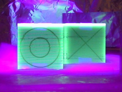
Orthogonally Layered Scintillating Glass Fiber Optic Cube
How the Material Works
High-energy radiation deposits energy in the scintillating glass and stimulates visible-light emission. In a fiber-optic scintillator, a portion of the emitted photons meets the total-internal-reflection condition and is guided along individual fibers toward the output surface. This combines radiation conversion with spatially confined light transport.
A reflective coating on the radiation-input surface can return otherwise lost visible photons toward the detector and may substantially increase output. EMA can be incorporated into the fiber matrix to reduce lateral light spread and preserve contrast.
Where Fiber Optic Scintillators Can Help
Representative application areas include:
- Industrial X-ray imaging and inspection
- High-energy radiography
- Imaging in geometries where direct detector coupling is valuable
- Applications requiring custom thickness, shape, coating, or coherent light transport
- Hybrid screen development balancing output and resolution
- Radiation-detection research and specialized instrumentation
Product Forms
| Product Form | Description | Potential Advantages |
|---|---|---|
| Bulk scintillating glass | A non-fiber plate or custom-shaped part made from luminescent glass | Simple geometry, direct radiation conversion, custom thickness and finishing |
| Scintillating fiber optic faceplate | Coherent fused fibers with scintillating cores | Combines conversion with guided image transfer and high spatial sampling |
| Mirrored scintillating faceplate | Fiber optic scintillator with a reflective input-side coating | Increases collection of emitted visible light |
| Hybrid scintillator | Fiber optic faceplate or scintillator combined with a separate phosphor screen such as Gd2O2S:Eu | Can increase total output while retaining some fiber-based resolution and coupling benefits |
Relative Output at Different X-Ray Energies
| Plate / Screen Type | 25 kV | 50 kV | 100 kV | 150 kV |
|---|---|---|---|---|
| Scintillating faceplate | 1.00 | 1.00 | 1.00 | 1.00 |
| Faceplate with mirror on input | 1.57 | 1.57 | 1.58 | 1.58 |
| Faceplate with Lanex on input | 1.71 | 2.20 | 1.76 | 1.66 |
| Hybrid faceplate with GADOX:Eu phosphor | 5.67 | 6.97 | 4.50 | 3.68 |
| Lanex Fine intensifier screen | 2.65 | 2.71 | 1.57 | 1.21 |
Attribution: Dr. Clifford Bueno, Lockheed Martin. Values are normalized to the unmodified scintillating faceplate at each tube voltage. Data taken using a 50 mm square by 6 mm thick scintillating faceplate made from fused 10 µm fibers with 12% statistical EMA.
Comparative Resolution at 50 kV
| Plate / Screen Type | Maximum Reported Resolution |
|---|---|
| Scintillating faceplate | 18 lp/mm |
| Faceplate with mirror on input | 19 lp/mm |
| Faceplate with Lanex on input | 15 lp/mm |
| Hybrid faceplate with GADOX:Eu phosphor | 13 lp/mm |
| Lanex Fine intensifier screen | 14 lp/mm |
Attribution: Dr. Clifford Bueno, Lockheed Martin.
Reported Absorption Efficiency
| Energy (keV) | 12 mm Fiber Optic (%) | 0.15 mm GOS Screen (%) |
|---|---|---|
| 50 | 100 | 38 |
| 100 | 99 | 33 |
| 150 | 97 | 27 |
| 200 | 95 | 23 |
| 250 | 93 | 20 |
| 300 | 90 | 18 |
| 350 | 87 | 17 |
| 400 | 83 | 15 |
Beam filtered by 6 mm aluminum. Attribution: Dr. Clifford Bueno, Lockheed Martin.
Reported Conversion Efficiency
| Screen Type | Light Photons / Absorbed X-Ray Photon at 50 kV | At 20 kV |
|---|---|---|
| Lanex | 1634 | 486 |
| Min-R | 590 | 208 |
| Scintillating fiber optic | 88 | 33 |
Attribution: Dr. Hans Roehrig, University of Arizona.
Information to Include With an Inquiry
- Radiation type, energy range, spectrum, and dose rate
- Detector type, active area, spectral response, and coupling method
- Required spatial resolution, output, absorption, persistence, and frame rate
- Available thickness and package dimensions
- Need for fiber-optic image transfer, EMA, mirror, phosphor, or coating
- Radiation lifetime, temperature, vacuum, and environmental conditions
- Prototype and production quantities
Frequently Asked Questions
What is the difference between bulk scintillating glass and a fiber optic scintillator?
Bulk glass converts radiation to visible light throughout a solid plate. A fiber optic scintillator also channels part of the emitted light through discrete fibers, which can reduce lateral spread and preserve spatial information.
Why add a mirror?
Visible photons emitted toward the input side can be reflected back toward the output, increasing collected light. The benefit depends on coating reflectivity, absorption, geometry, and detector coupling.
Why use a hybrid phosphor-and-fiber structure?
A phosphor screen can increase output, while the fiber-optic substrate provides controlled light transport and direct coupling. The tradeoff is usually some loss of resolution or increased spread.
Are the published performance tables guaranteed?
No. They are legacy experimental data for specific samples and test conditions. Current project performance should be evaluated using the required geometry, energy spectrum, detector, and acceptance criteria.
Discuss a radiation-conversion requirement
Send the energy range, detector, active area, thickness, resolution, output target, environment, and quantity. CHI can help identify whether bulk, fiber-optic, mirrored, or hybrid construction is worth evaluating.
Discuss an X-ray or radiation-detection application