Products
Image Conduits, Multi-Fiber Light Guides and Remapping Devices
CHI builds coherent and noncoherent fiber structures that transfer images, route illumination, reshape an optical field, or rearrange spatial information between an input and an output that cannot be connected with a simple lens or window.
CHI builds coherent and noncoherent fiber structures that transfer images, route illumination, reshape an optical field, or rearrange spatial information between an input and an output that cannot be connected with a simple lens or window.
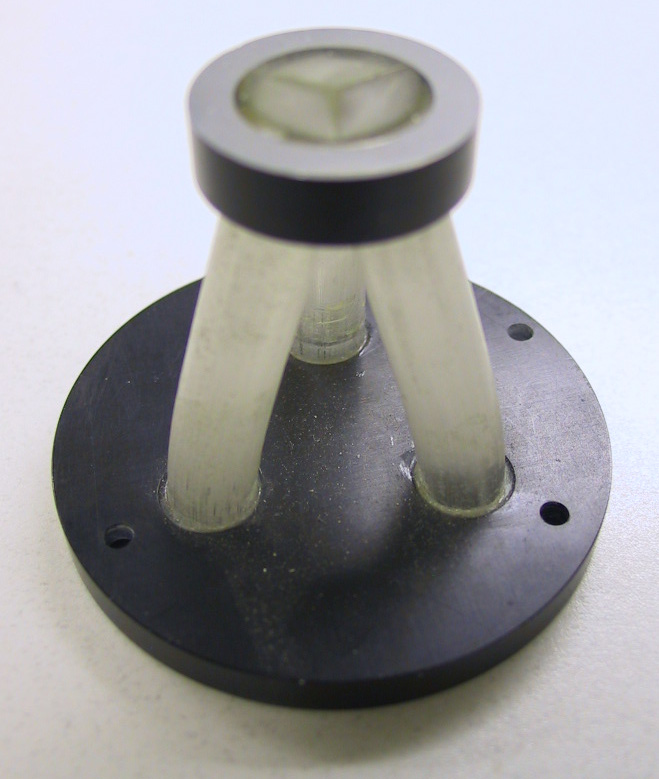
Three-leg Fiber Optic Splitter-Combiner
Image Conduits
An image conduit is a coherent bundle, usually fused, that transmits an image from one end to the other. Standard overall conduit diameters range from approximately 0.1 to 25 mm. Larger conduits are commonly 5–150 mm long, while smaller diameters may extend several feet. These are representative ranges, not fixed limits.
Constituent-fiber diameter is a primary resolution variable. Numerical aperture controls accepted ray angles, OAR controls active area, and EMA can reduce stray-light cross-talk. Larger fused conduits become relatively rigid, but they may be permanently formed to a required bend, path, or route during manufacture.
Multi-Fibers and Light Guides
A multi-fiber may contain a small number of fibers or hundreds of thousands of them. Fibers can be packed in square or hexagonal arrays and drawn into circular, square, hexagonal, or custom exterior shapes. Depending on coherence and optical requirements, the structure can transfer positional information or serve as an illumination guide.
Constituent fibers smaller than approximately 1–3 µm can lose visible-light efficiency if the cladding becomes too thin to maintain effective total internal reflection. Lowering the core OAR can improve isolation by increasing cladding thickness, but it also reduces transmitting area. The optimum is application-dependent.
Geometry Conversion and Remapping
A geometry converter transforms light or an image from an input field of one size or shape to an output field of another. A simple device may taper a circular field to a smaller circular field on the same axis. A more complex remapping structure may move multiple input zones to different output positions, combine fields, separate fields, or change both shape and scale.
These components are application-specific. Early discussion of the detector, source, field geometry, allowable distortion, fiber count, routing, and packaging is essential because the mapping architecture determines the preform, assembly, draw, fusion, and finishing process.
Choose the Structure by Function
| Structure | Primary Function | Typical Characteristic |
|---|---|---|
| Multi-fiber | Building block for larger fused-fiber components; may carry positional information or illumination | A few to hundreds of thousands of fibers packed into a controlled exterior geometry |
| Image conduit | Transfers a coherent image from one end to the other | Relative fiber positions are preserved; resolution depends on constituent-fiber diameter |
| Light guide | Routes illumination without preserving positional information | Fiber arrangement can be optimized for collection, routing, mixing, or output shape |
| Geometry converter | Changes field size or exterior geometry between input and output | Examples include round-to-square or large-to-small tapered transitions |
| Image remapping device | Rearranges selected spatial regions or multiple fields | Custom input fibers or zones terminate at different output positions or geometries |
Design Variables
- Input and output field dimensions and shapes
- Whether spatial coherence must be preserved
- Required resolution or constituent-fiber diameter
- Numerical aperture and source/detector coupling
- OAR, EMA, contrast, and allowable cross-talk
- Overall length, route, bend, and rigidity constraints
- Magnification, taper, field rearrangement, or channel mapping
- Surface polish, coating, bonding, housings, connectors, and alignment features
- Prototype and production quantities
Frequently Asked Questions
What is the difference between an image conduit and a light guide?
An image conduit preserves the relative position of its fibers so an image can be reproduced at the output. A light guide primarily transports illumination and does not typically preserve spatial mapping.
Can CHI make a round-to-square converter?
Potentially, yes. Round, square, hexagonal, tapered, and other geometry transitions are natural candidates for custom fused-fiber design.
Can an image conduit be flexible?
Small-diameter fibers or bundles can have some flexibility, similar to that of a solid glass rod of equivalent diameter. Larger fused conduits are comparatively rigid and are usually permanently formed to the required route rather than repeatedly flexed.
Can multiple input regions be rearranged at the output?
Yes. That is the purpose of a custom image-remapping device, although the complexity and development effort increase with channel count, mapping precision, and packaging constraints.
Describe the input and the output
Send the two field geometries, required mapping, resolution, NA, route, environment, interfaces, and quantity. CHI can evaluate whether a fused-fiber solution is practical.
Discuss an image-routing or geometry-conversion need